
The conversion of this camera is a bit difficult. You need to remember which screw goes where and there are a logic board and a metal frame to take out before we can access the sensor.
We will use small flat and Philips screw drivers, tweezers and scissors. I suspect those screw lengths and which one goes where are important and there is a chance if you mix them the camera would not power on. This trick they implemented on Canon EOS M. If you mix screws on the right side the camera will power on but will not take photos. That’s how they got smart in making cameras.
Unscrew all outside screws. I suggest placing them on the table according to their location in the camera. Take out the rubber cover on the left side. Simply forcefully pull it off. It should go out somewhat easy as the screws are already out and the plastic that keeps it in place is loose.
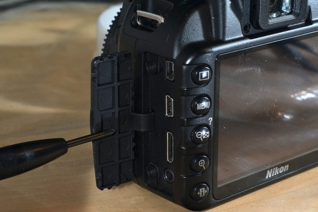
Unscrew the two screws in battery compartment. Take out the red plastic piece and remove rubber grip cover.
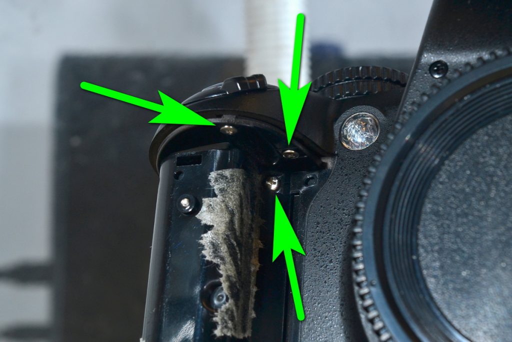
Unscrew the three screws that are on the upper part.
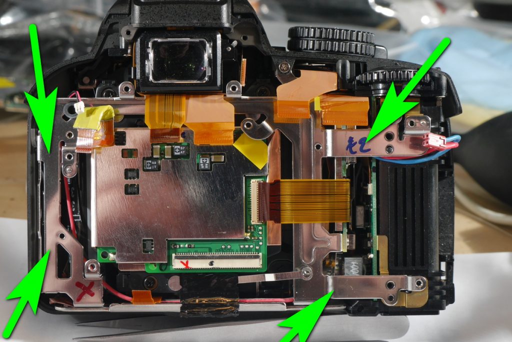
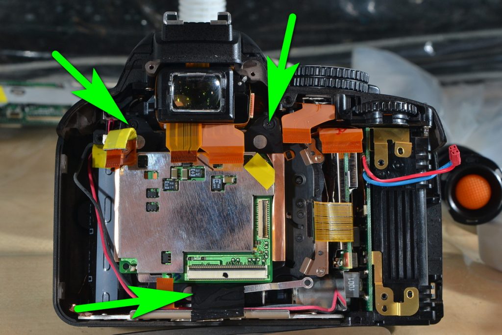
Unscrew two screws that hold the back plastic. Carefully separate the back plastic piece from the camera. There will be a ribbon cable to disconnect. Now disconnect all the ribbon cables. Unscrew all logic board screws and lift it.
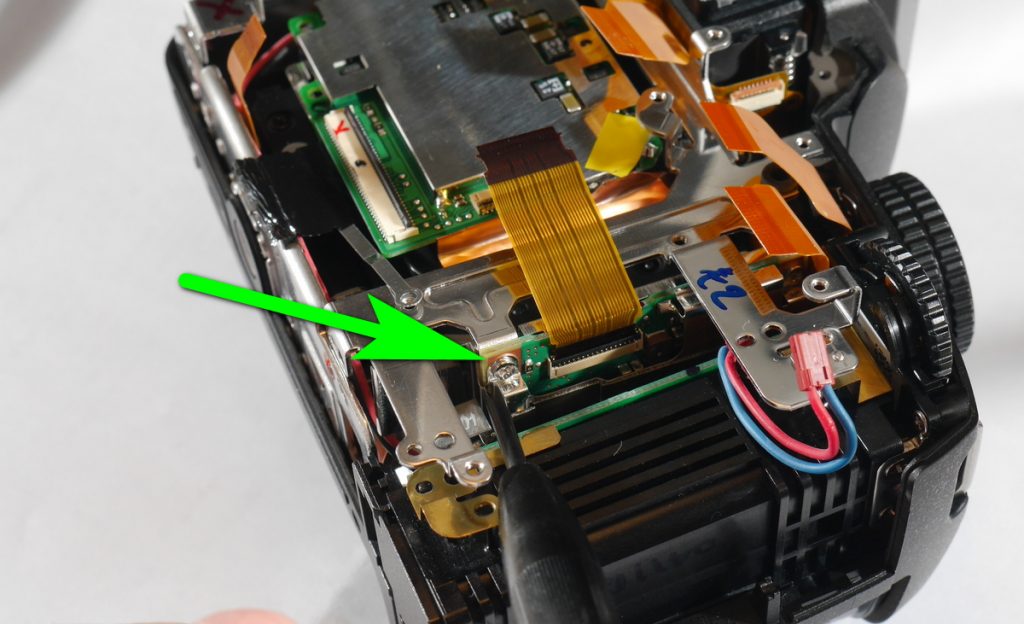
Underneath the logic board there will be a wide ribbon cable. Disconnect that cable from the logic board. Mark with a marker which cable end goes where.
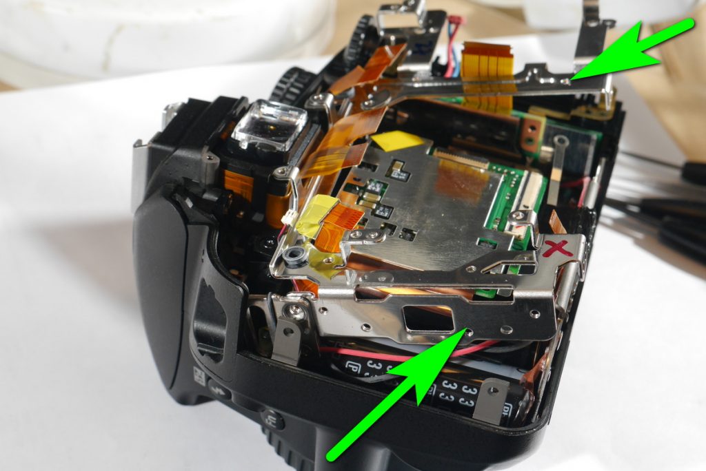
Unscrew three screws on a metal plate. Take out that metal plate. Remember where that ribbon cable goes on the left upper side. It must go underneath that metal plate and not between logic board and the metal plate.
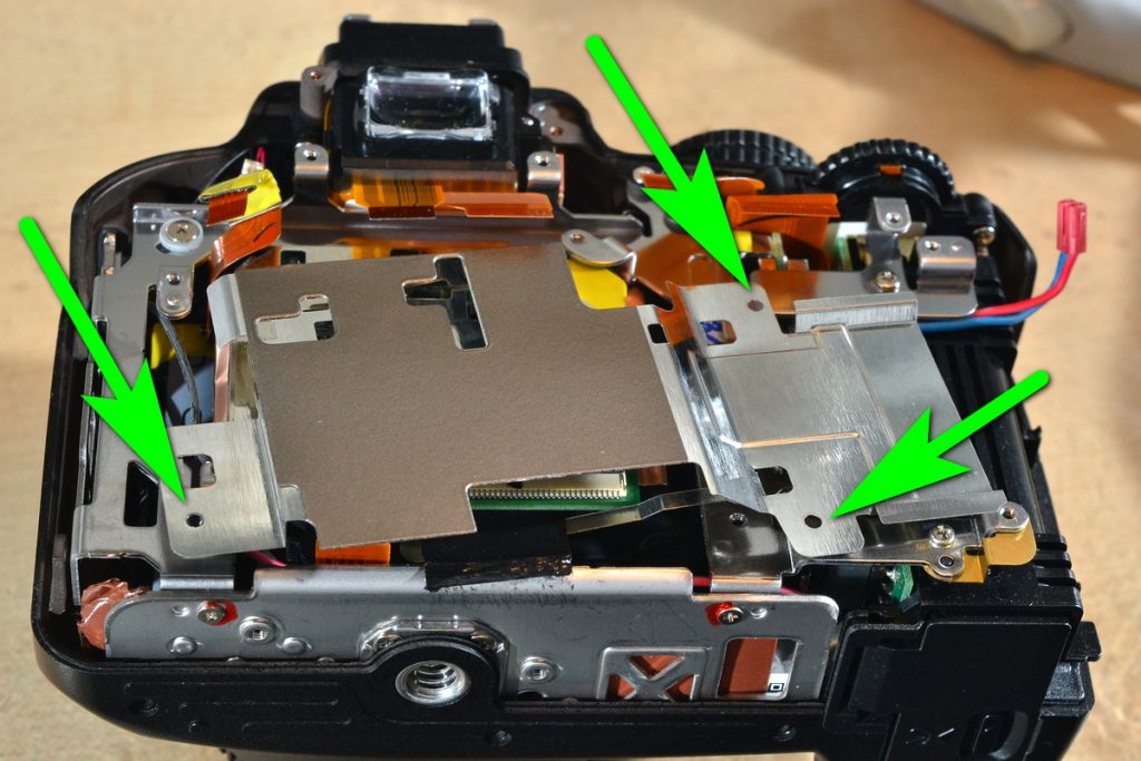
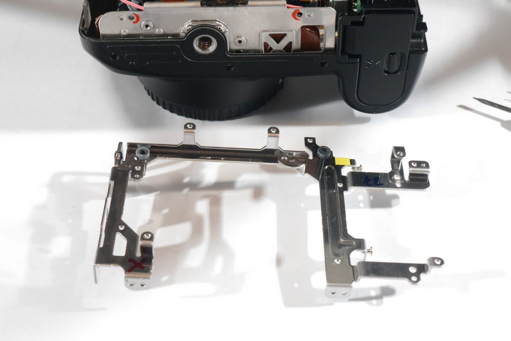
Now we need to take that metal frame. Unscrew the screws and lift a bit the upper side. There will be another small PCB attached to this metal frame. When you lift them you will see the two screws holding it. Unscrew them and now we can take out the frame. With a flat screw separate the frame from the camera at the bottom.
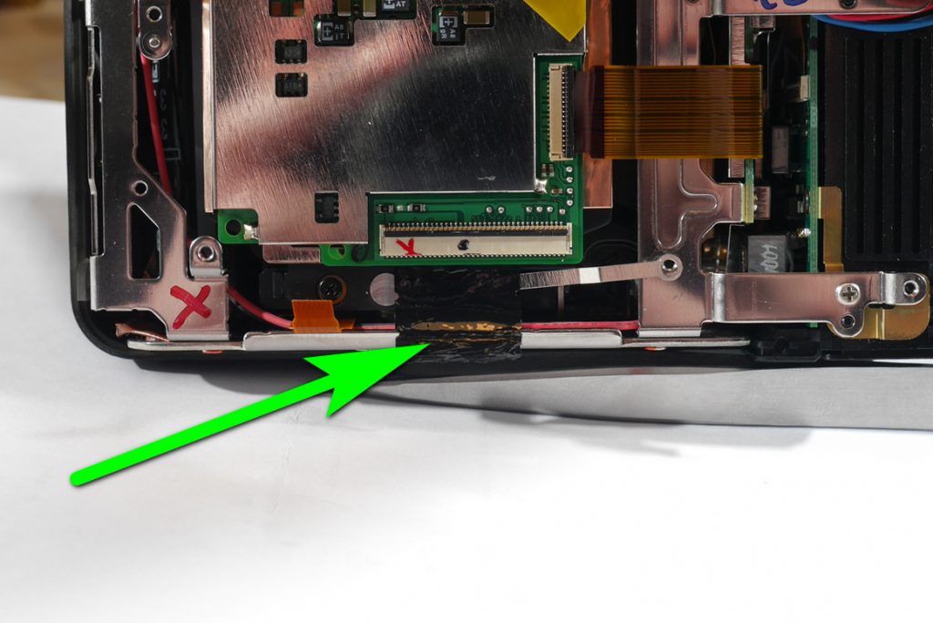
There will be a conductive tape that goes from the sensor to camera chassis. Separate the tape using a small flat screwdriver. Disconnect any flat ribbon cables that are left.
Unscrew three sensor screws. Start lifting the sensor from the right side. You will notice shims for each side. Try not to lose them. When you lift the right sensor side you can pull the left side also. There is a sticky plastic on the left side that prevents the left sensor side from lifting.
Take out the shims and remember which one goes where. They are not the same thickness.
In case those shims are different in thickness I suggest putting them back when assembling as they help to level the sensor.
Now we need to separate that cleaning system cable from the sensor. One way is to simply de-solder it. The other way is to pull it until it cracks and it will separate from the soldering point.

Just use a small tweezers and push the cable to the sides near the soldering point. Eventually a crack will appear and the cable will disconnect from the soldering point.
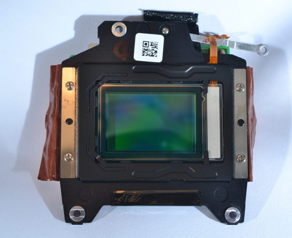
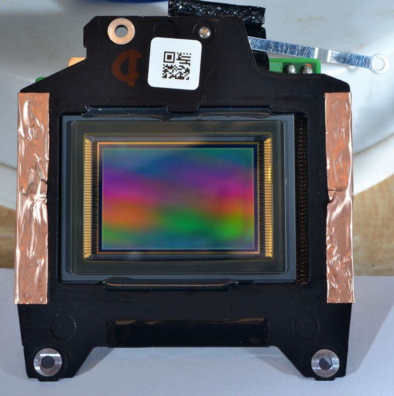
Now we can unscrew filter frame screws and take out the UV/IR cut off filter.
The sensor is still protected with a glass so we can use the sensor as it is.
If you want to be pedantic you can move the sensor to the front by 0.3 mm to make the quick focusing work precisely. Depending on the thickness of those shims you may just assemble without shims. That will shift the sensor a bit to the front.
Fit in the sensor and stick the conductive tape to camera chassis with a piece of cello tape.
Please remember if you lose shims they tend to stick somewhere in the camera or in your room. I once could not find one shim for one hour as it was stuck on the conductive tape.
Download Our Infrared Photography Guide

- How to take infrared pictures with a digital camera
- What are infrared filters available
- How to process infrared images
- How to modify a digital camera for infrared photography
- How to modify a digital camera to a full spectrum
 Subscribe to our YouTube channel